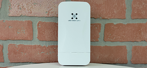
Led Sign City Series 6X38 outdoor custom led sign with brilliant full-color programmable digital signage, Free software, and wireless communication

Table of Contents
What's on This Page (10 Sections)
Here's what the page covers—each section is numbered and matched to the content below so you can scroll or jump to what you need:


Product Spotlight: 6x38 Outdoor Custom LED Sign
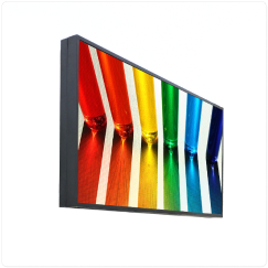
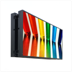
Ignite your business growth with the LED Sign City 6x38 Outdoor Custom LED Sign—a vibrant, full-color display that commands attention and converts passersby into customers. Designed for maximum visibility with ultra-bright LEDs and high-resolution visuals, this sign is easily updated with our FREE wireless software, keeping your messaging fresh and effective. Enjoy manufacturer-direct pricing, a 15-year warranty, and upgradeable components that future-proof your investment.
Design your sign, get instant pricing, and place your order online today!
Key Specs at a Glance:
-
3 resolution options, up to 525312 pixels per side | Brightness levels up to 10,000 NITS
-
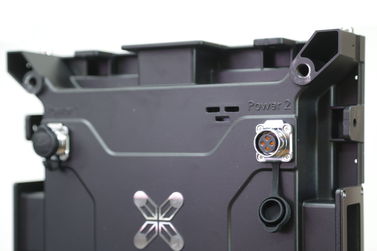
Double-sided display | WiFi standard with optional 4G
-
DIY or turnkey installation | Warranty: 5 to 15 Years
-
Power: 196.9 AMPS @ 110V | Lead Time: 6–8 weeks
Feature Highlights
-
Stunning Visuals: Up to 2304 pixels per module deliver vivid, high-resolution imagery.
-
Ultra Brightness: 7000–10000 nits ensure visibility, even in direct sunlight.
-
Wide Viewing Angles: Your message is clearly visible from multiple directions.
-
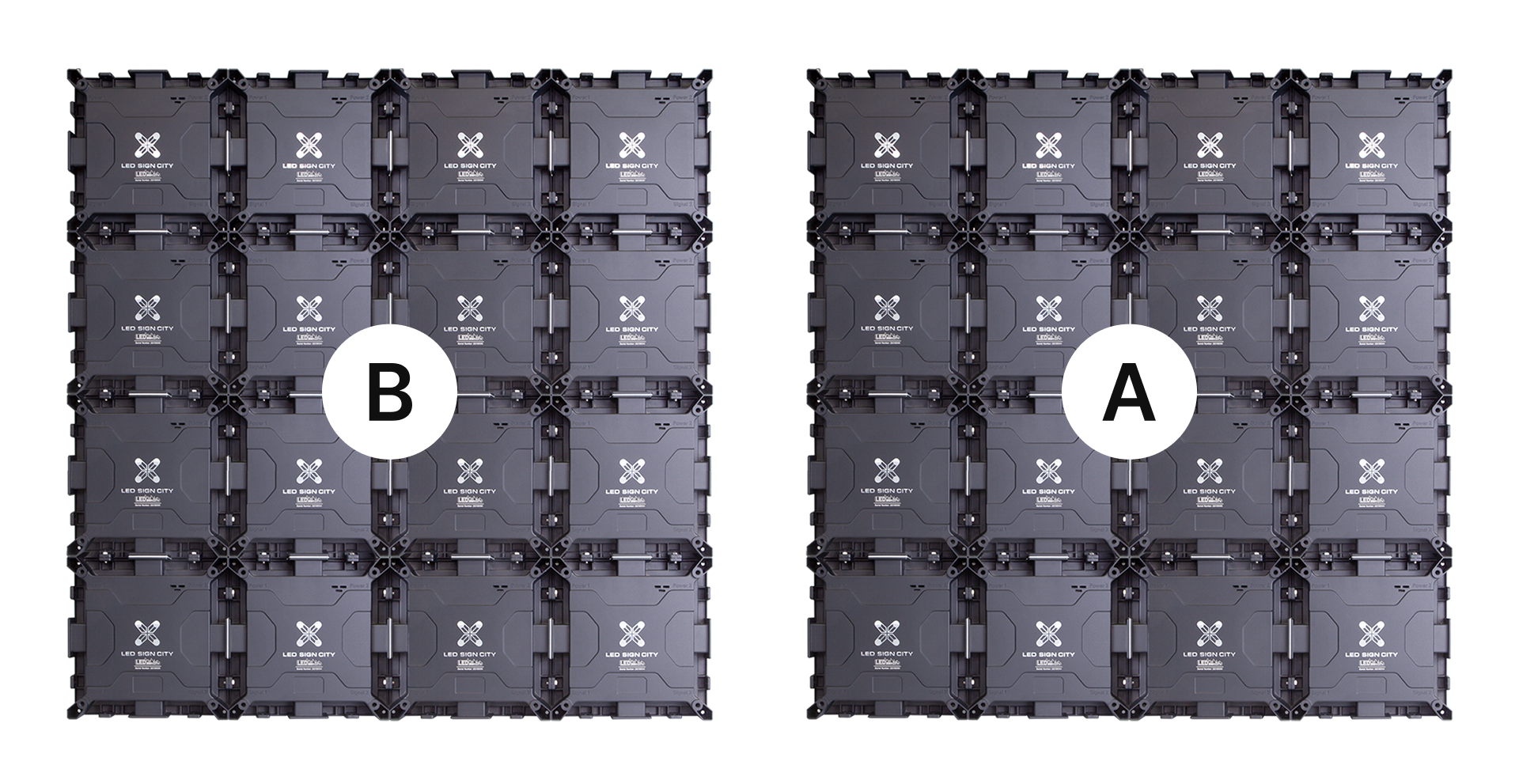
Flexible Sizing: Modular design allows for virtually any custom size.
-
Wireless Updates: Control your sign from your phone, tablet, or computer.
-
Free Smart Software: Easy design and scheduling—even for beginners.
-
Energy Efficient: Automatic brightness sensors reduce energy costs.
Find the perfect balance of resolution, brightness, and installation style with the LED Sign City Series 6x38 Outdoor LED Sign. Everything you need—from product selection to setup—is right here on this page.
This powerhouse delivers exceptional visibility. Available in single or double-sided configurations, the 6x38 LED sign offers a resolution of up to 288 x 1824 pixels—that's 525312 total pixels per side—for crisp, full-color content that stands out day or night. Choose from multiple resolution and brightness options, including models reaching up to 10,000 NITS for excellent performance in direct sunlight.
Beacon HD: P6 MM
Pixel density:
2304 Pixels
Display Resolution:
288 pixels x 1824 pixels
Brightness:
Beacon HD 7000 Nits Beacon HD Pro 8000 Nits
Beacon: P8 mm
Pixel density:
1600 Pixels
Display Resolution:
240 pixels x 1520 pixels
Brightness:
Beacon 7500 Nits Beacon Pro 8500 Nits
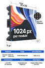
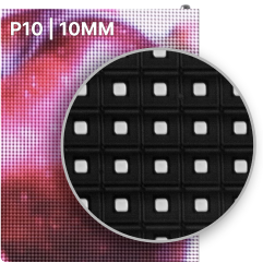
Spotlight: P10 mm

Pixel density:
1024 Pixels
Display Resolution:
192 pixels x 1216 pixels
Brightness:
Spotlight 8500 Nits Spotlight Pro 10000 Nits
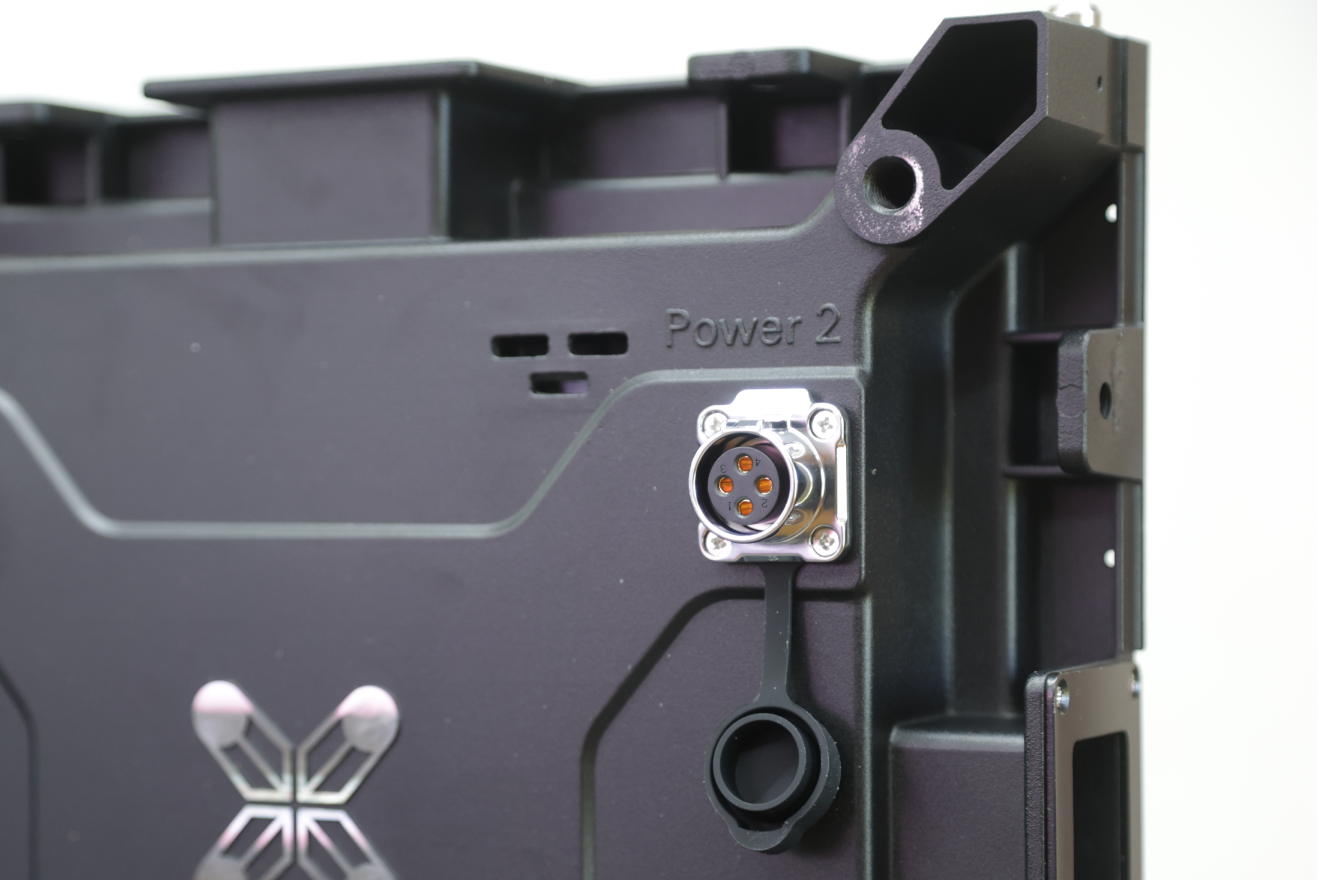
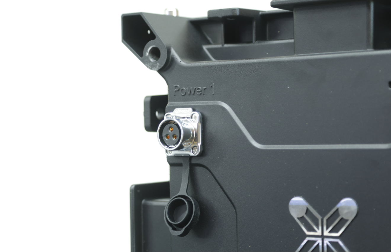
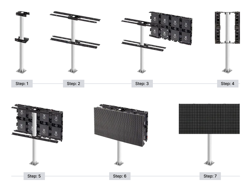
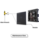
Built for flexibility, the 6x38 supports both DIY installation and turnkey setup, allowing you to take control or leave it to the pros. It draws 196 AMPS @ 110V (or 98 AMPS @ 220V) and weighs approximately 2280 lbs per side.

Cabinet Weight:
10-lbs. / sq ft.
Max weight:
(6x38)x10 = 2280 lbs/side

Power use:
95 Watts / sq ft.
196 AMPS@110V or 98 AMPS@220V / Side
Power consumption:
Max 21660 watts
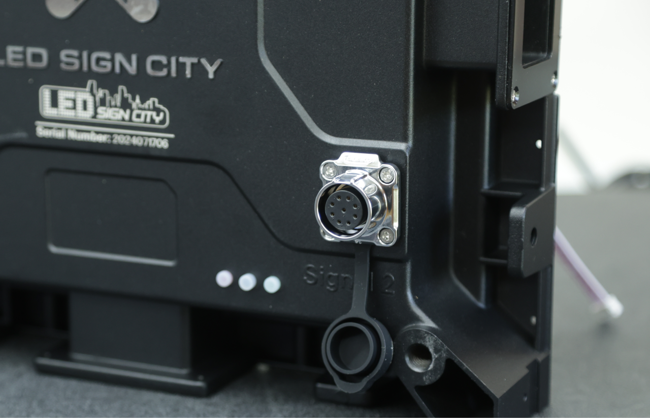
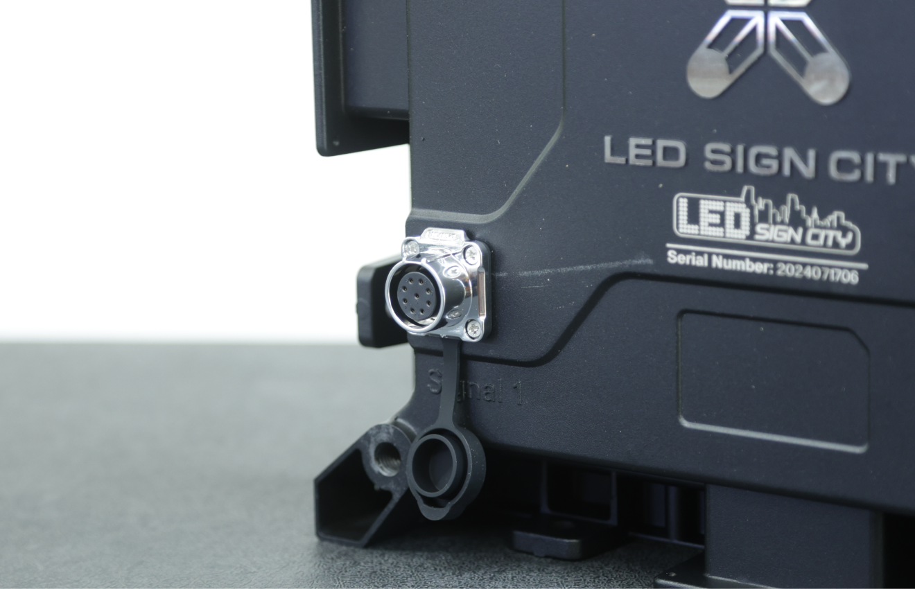
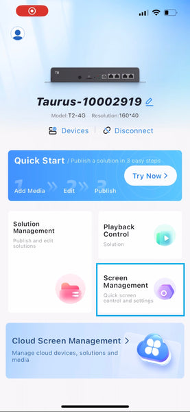
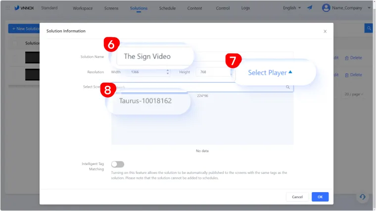
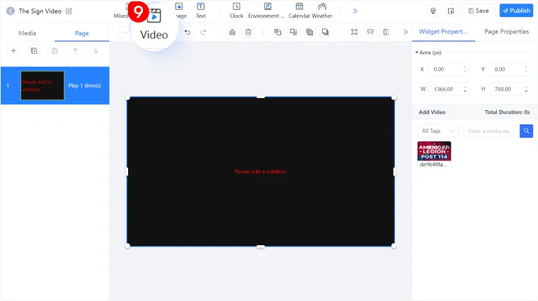
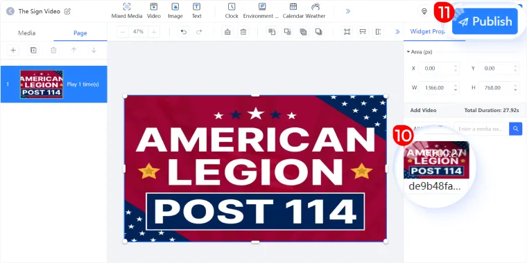
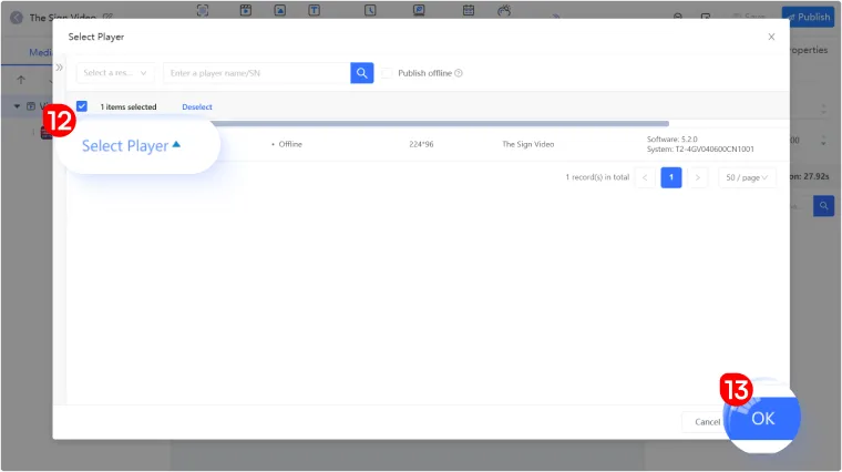
Content is easy to manage with our free smart software, which allows you to schedule slideshows, stream video, and display live elements like weather, clocks, or countdowns—from your phone, tablet, or computer.

Media Support:
Images, Videos, Slides, and more.

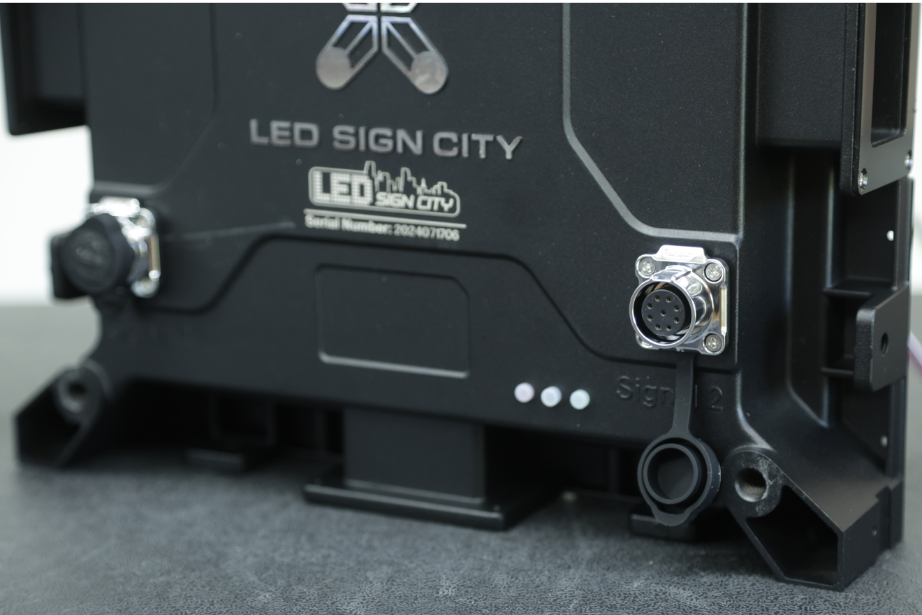
Communication:
LAN, WIFI, 4G (Optional)

Automatic Sensors:
Temperature and Brightness
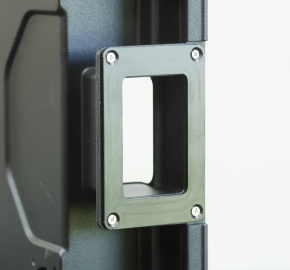
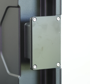
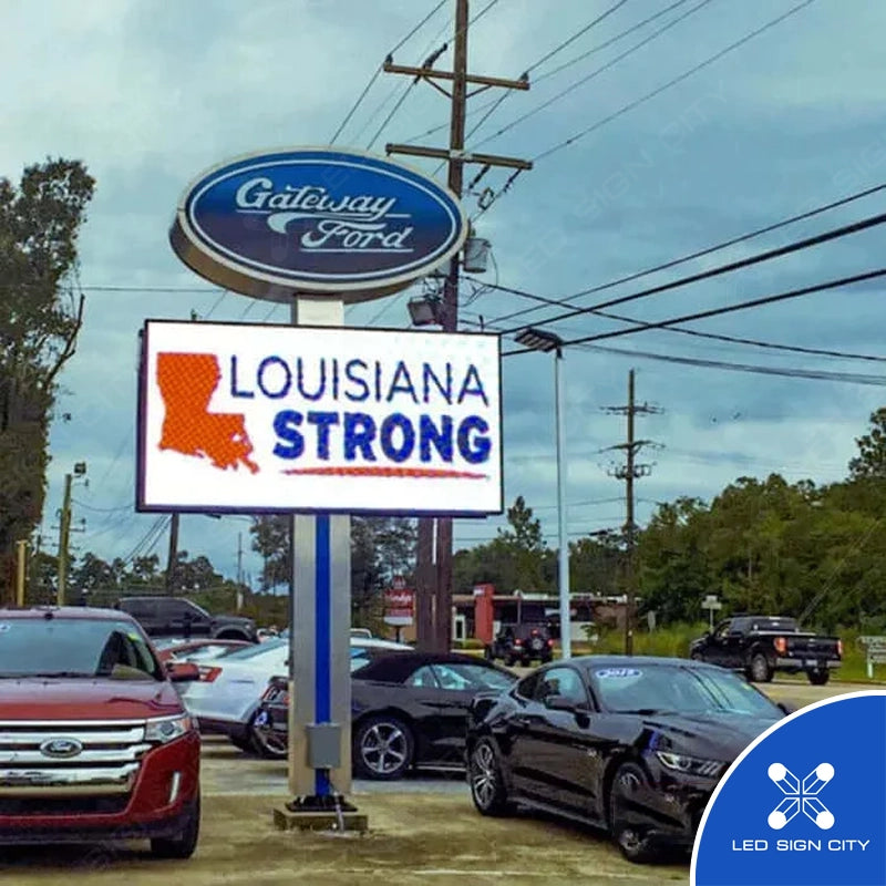
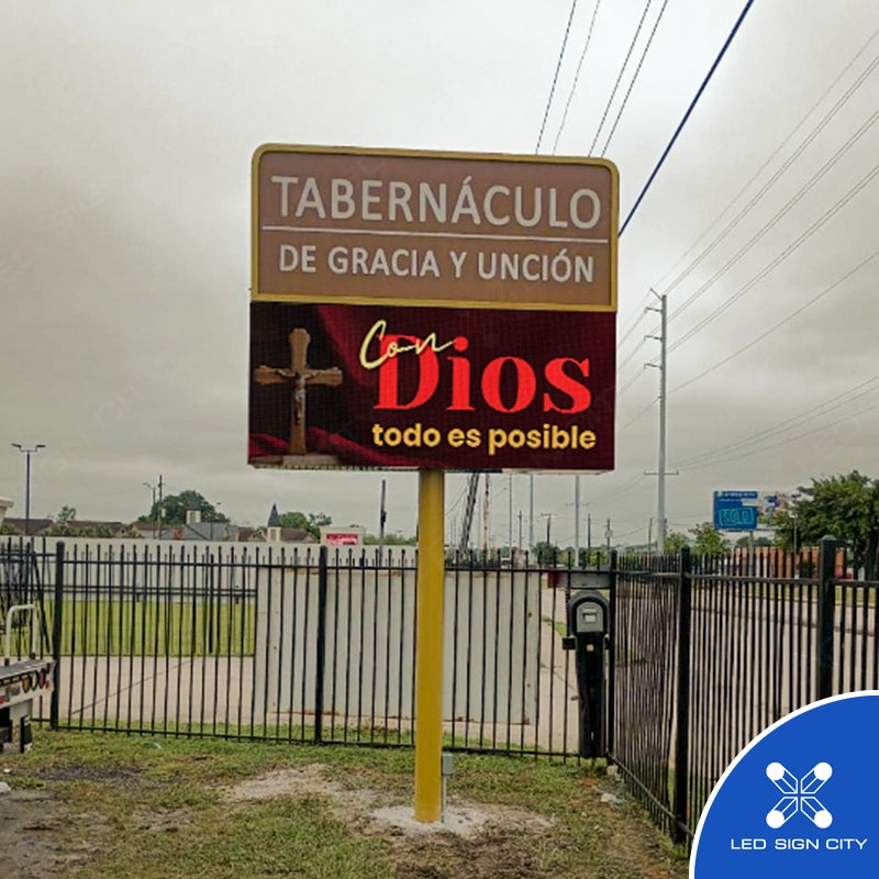
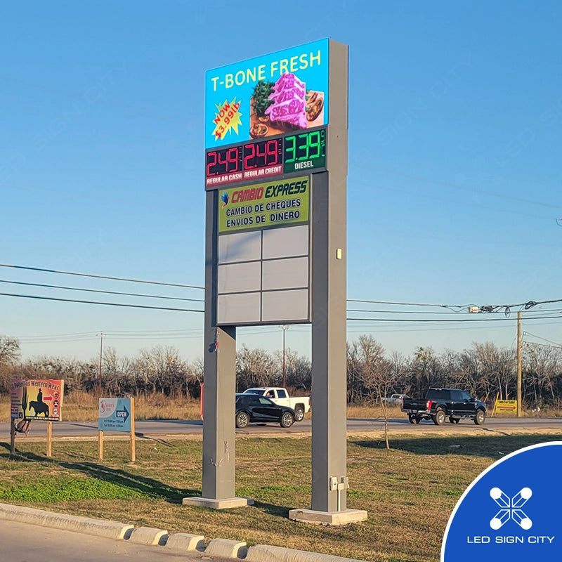
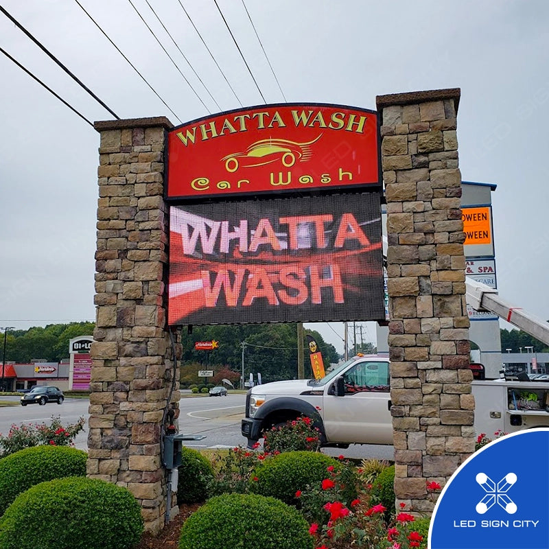
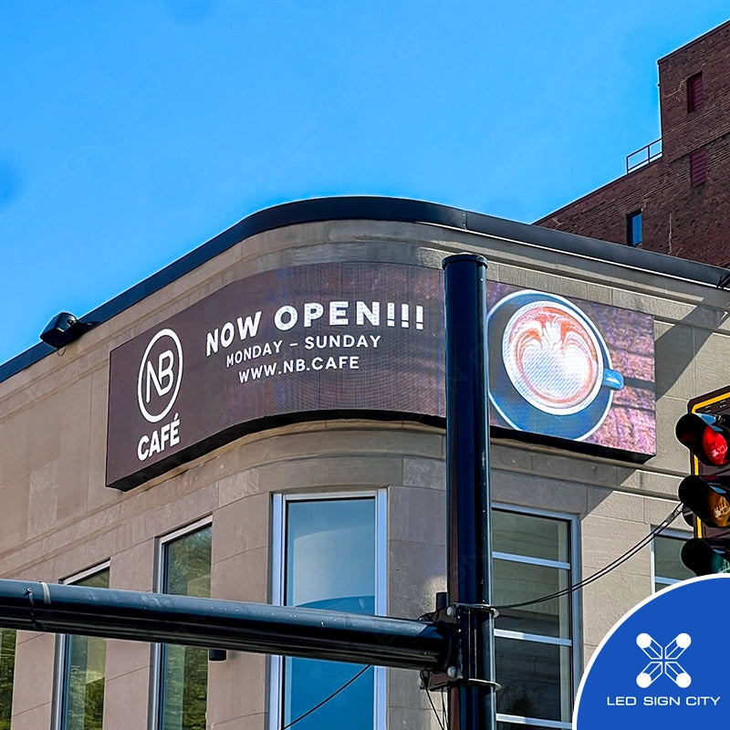
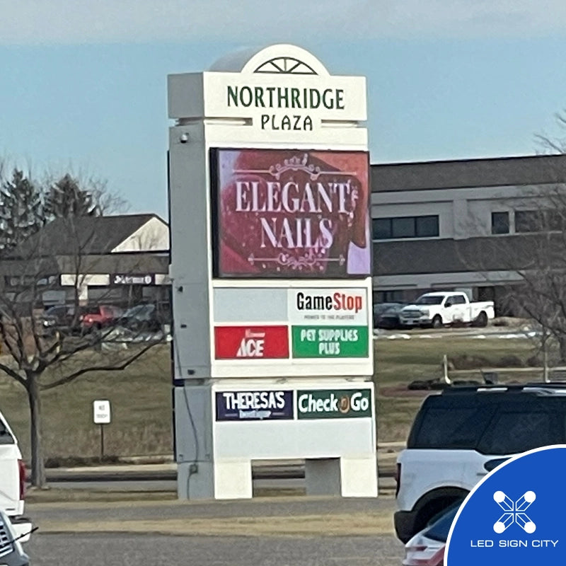
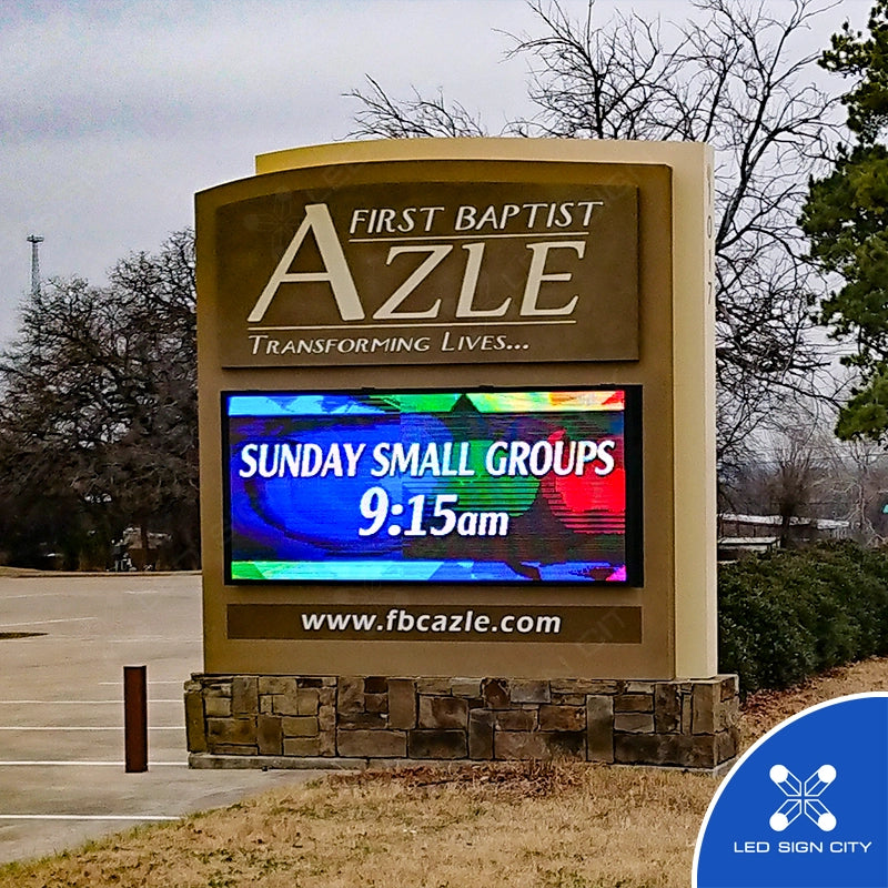
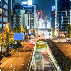
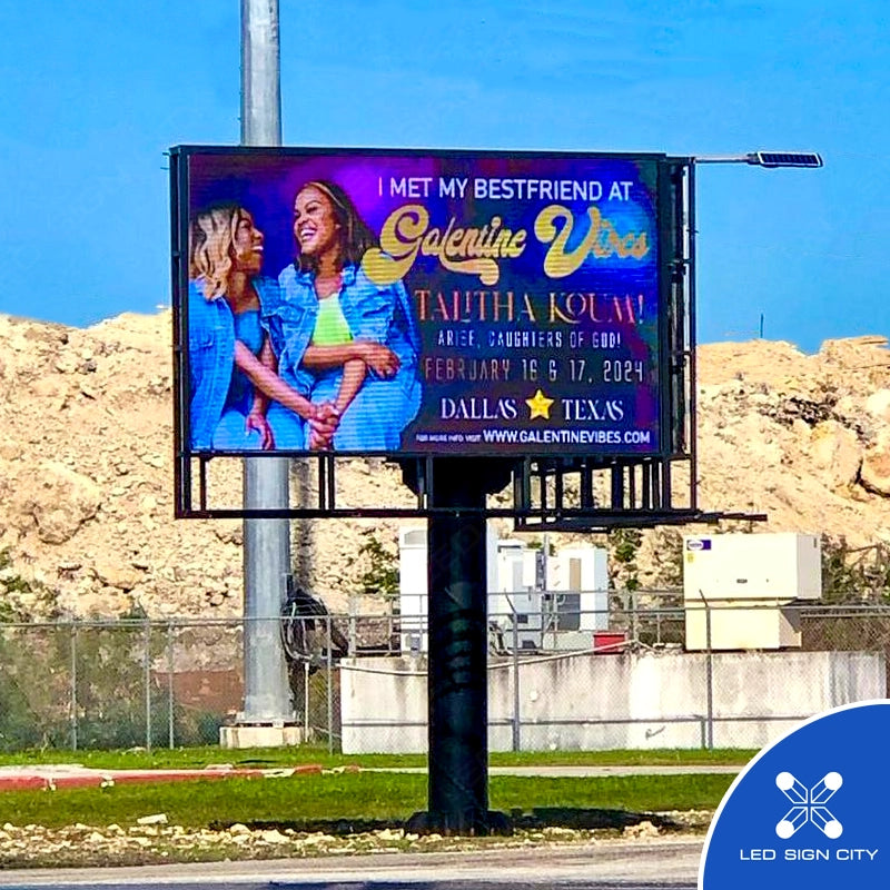
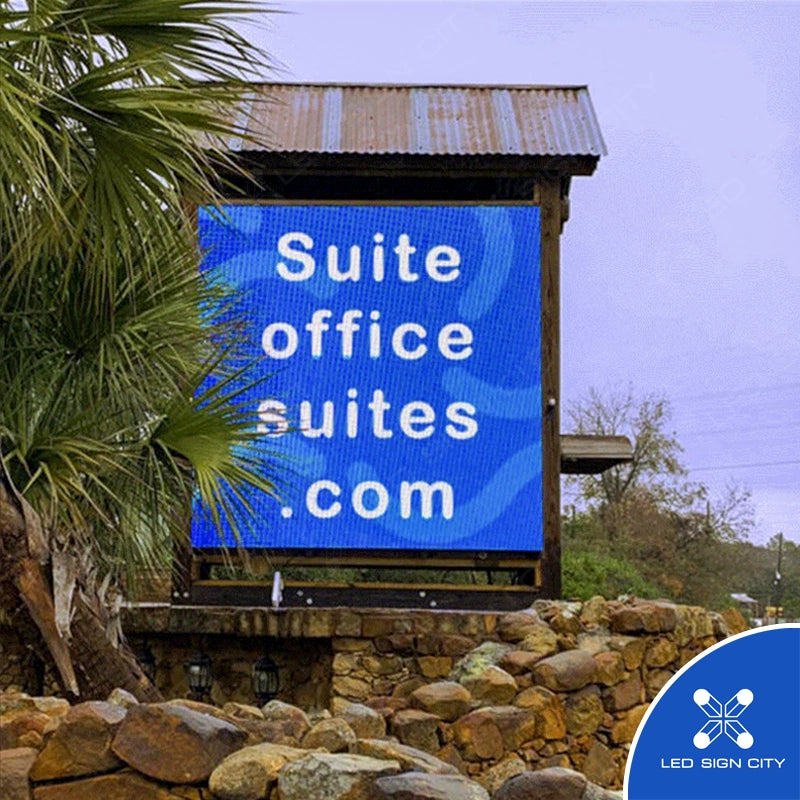
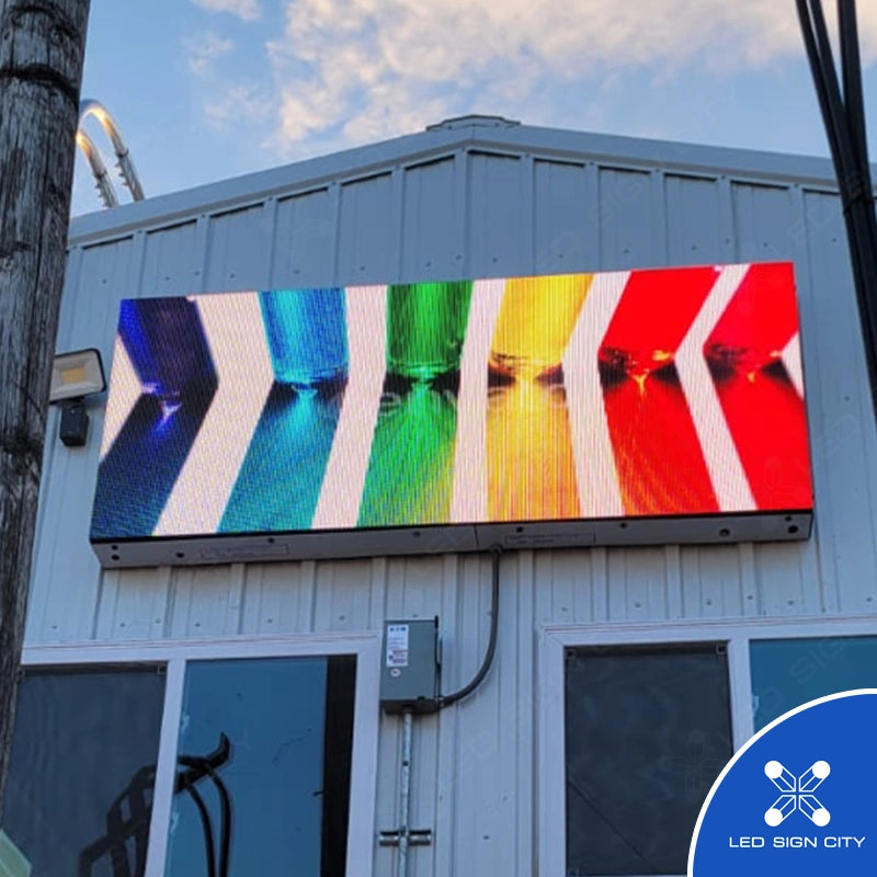
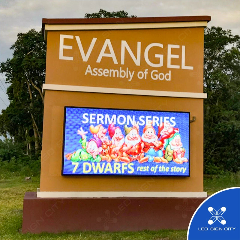
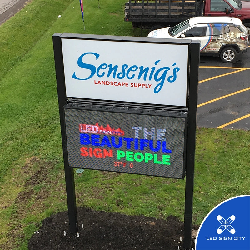
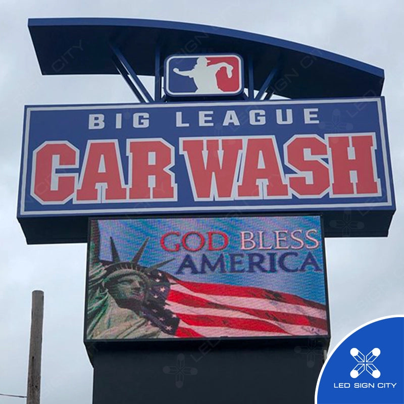
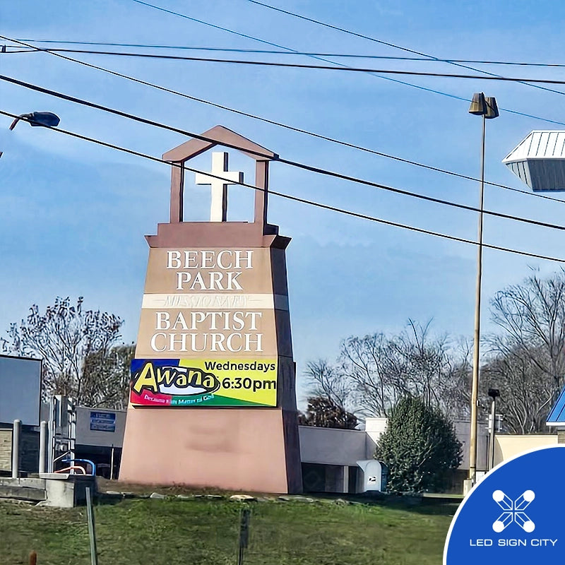
See It in Action: Installation Styles
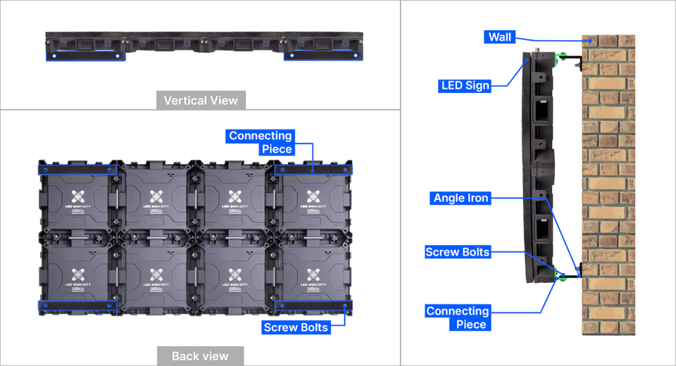
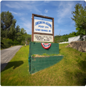
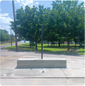
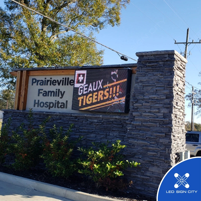
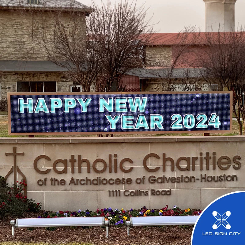
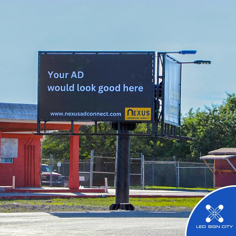
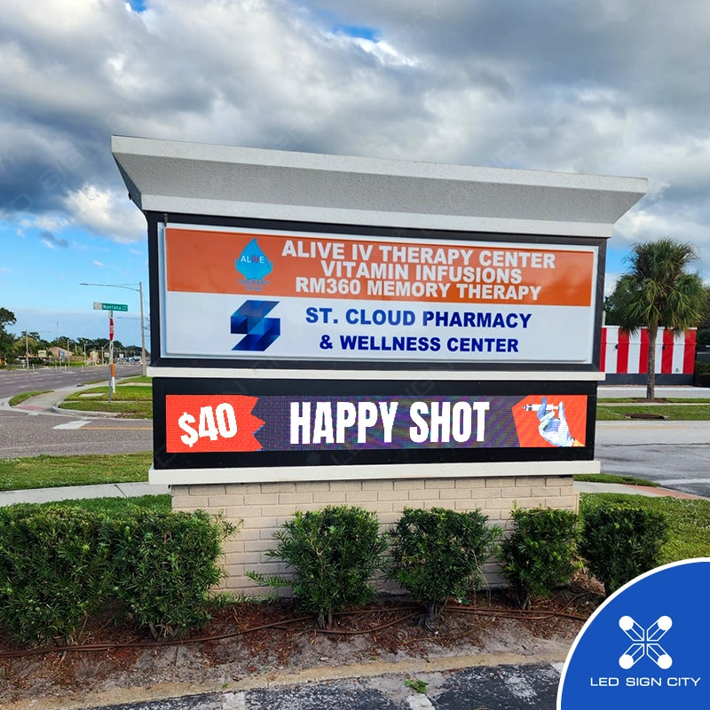
Our LED signs are designed to fit a wide range of installation environments. Whether you're mounting to a building, elevating on poles, or integrating into a monument, these are the most common styles you'll see across our projects:
-
Wall Mount: Attached directly to a flat building surface.
-
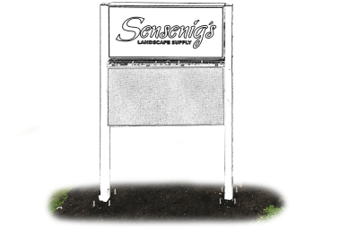
Single Pole: Mounted on a single center pole for elevated visibility.
-
Dual Pole: Supported between two poles for enhanced balance and presence.
-
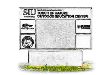
Monument Mount: Framed within a monument base or custom structure.
Browse the gallery below to explore real-world examples of each mounting style.
Installation Preference
Self-Installation (DIY)
Customer is responsible for installation and setup.
Full-Service Installation (Turnkey)
Ideal for businesses that want a hassle-free experience.
Do You Have an Existing Sign or Are You Building a New One?
Upgrading an Existing Sign
Enhance or replace your current signage with a modern LED display.
Already have a sign structure in place? Upgrading allows you to maintain your existing footprint while benefiting from a brighter, more dynamic display.
Building a New Sign
Create a brand-new sign designed specifically for your needs.
No existing sign? No problem! We offer complete signage solutions, including structure design, permitting assistance, and professional installation.
Do You Have an Existing Structure for the Sign to Be Mounted To?
Yes:
You can install the sign on my existing pole, wall or monument.
No:
I will need a new foundation and pole or monument.
Select Your Preferred Installation Type for Existing Structure
Choose the installation style that best fits your existing structure.
Wall Mounted
Best for: Existing wall structures on storefronts, restaurants, and urban businesses.
Retrofit Existing Pole
Best for: Replacing outdated signs on existing poles or structures.
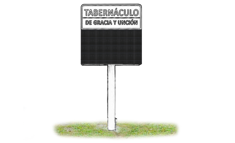
Monument Retrofit
Best for: Upgrading existing monument signs for business parks, schools, and community centers.
Select Your Preferred New Installation Type
Choose the installation style that best fits your business needs. Each option includes a brief description to help you decide.
📍 Single Pole
Best for: Roadside businesses, gas stations, and retail locations.
📍 Double Pole
Best for: Large signs, shopping centers, and industrial areas.
🏢 Wall Mounted
Best for: Storefronts, restaurants, and urban businesses.
🏛️ Monument
Best for: Business parks, schools, and community centers.
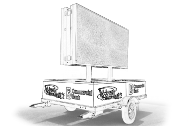
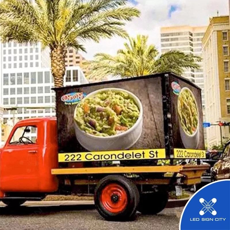
🚚 Trailer-Mounted
Best for: Construction sites, events, and pop-up advertising.
Which option best describes the sign you want to build?
Programmable
LED Sign
Programmable LED Sign & Light Box
Display Visibility: How Do You Want Your Sign Seen?
One / Single Sided
Two / Double Sided
Display Brightness: Which Option Suits Your Environment?
Mixed-Use
Residential or Commercial
Commercial
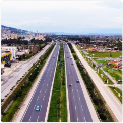
Highways and Freeways
Display Clarity: Choose Your Ideal Resolution
Good - Spotlight Series
- Good images & videos
- 1024 pixels/module
- 8500 NITS
Better - Beacon Series
- 1.56X Clearer than Spotlight
- 1600 pixels/module
- 7500 NITS
Best - Beacon HD Series
- 2.25X Clearer than Spotlight
- 2304 pixels
- 7000 NITS
Good - Spotlight PRO Series
- Good images & videos
- 1024 pixels/module
- 10000 NITS
Better - Beacon PRO Series
- 1.56X Clearer than Spotlight
- 1600 pixels/module
- 8500 NITS
Best - Beacon HD PRO Series
- 2.25X Clearer than Spotlight
- 2304 pixels
- 8000 NITS
Sign Dimensions: Customize Height and Width
Sign Dimensions: Customize Height and Width
Display Height
Display Width
Enter the dimensions of your light box
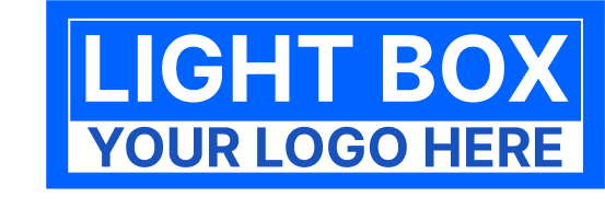
Enter the dimensions of your light box
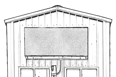
A light box is a static, backlit sign with your company name or logo printed on it.
Light Box Height
We've had our sign for over 4 years and the customer service has been AMAZING!!! We call Shane for all issues and he has been so good at helping us with technical and actual sign issues. Our sign has only had minor issues but LED Sign City has fixed them every time quickly and efficiently. The sign is super easy to program and would definitely recommend it if you are thinking of buying one.

Our church saved a lot of money with LED Sign City and we could not be happier with our purchase. Our order was delivered safely, well packaged, and ahead of schedule. The service before, during, and after the sale was prompt and first class. Very happy and would certainly deal with again in the future.

I had an outstanding experience with Sign City! Shane was very helpful and knowledgeable, and he provided fantastic customer service. I highly recommend them for their product and their service!

Great Sign! I looked around for a led sign to put in front of the store for promotions to be displayed for a while. Led sign city was the best price and quality for something we could program and control. I can't say enough about the great service and support they provided as well. Shane was particularly helpful in getting us up and running. Thank you!

I recently had the pleasure of working with LED Sign City and I must say, I am thoroughly impressed. From start to finish, their customer service was top-notch. Shane and Kelli were particularly helpful during the entire process. They were always available to answer any questions I had and went above and beyond to ensure that my needs were met.
The quality of their LED products is outstanding. The signage they provided for my business is durable, bright, and eye-catching. It has truly elevated the appearance of my storefront and has already caught the attention of many potential customers.
Working with LED Sign City was an overall fantastic experience. Their dedication to providing excellent customer service and high-quality products truly sets them apart from other companies in the industry. I highly recommend them to anyone in need of LED signage for their business.
Thank you again, Shane and Kelli and all of LED Sign City, for all your help. I look forward to working with LED Sign City in the future for all my LED signage needs!

It's a Great pleasure working with People like that. Very Patient and friendly staff. I'll Recommend it to look forward to try it. Excellent Service and great knowledge.

I have worked with Shane and LED Sign City for almost a year. We purchased and installed a 3' x 6' double-sided sign for our church. We could have worked with a better company or a better person. Shane has never failed to answer our questions and give us direction. We had a warranty issue a couple of weeks ago and it was a very smooth transaction and the help with troubleshooting the issues was great. I HIGHLY RECOMMEND SHANE AND LED SIGN CITY!!!!!

LED Sign City has been awesome! Here at Believers Temple COGIC, we are very pleased with our sign. Assembly was minimal, and online support has been very helpful. The graphics are great! Big thanks to Shane and his team!

This company is TOTALLY Legit!!! Best customer service out there! Shane is patient, knowledgeable and very helpful. If you are looking for an LED Sign, then I HIGHLY recommend this outfit!

Great experiences! Shane Ramone has come through for me MANY times and is always so patient and respectful. He is a real pleasure to speak and work with. Hats off to LED Sign City and Shane! Jennie Minter

More Reviews
This is one of best designing team I ever deal with! I am so happy with service they provided me [with the 5x10 foot LED sign and the video ads for the sign]! All my projects will go to this company. I highly recommend them
Our company, IceWorks Skating Complex, had a tremendous experience with LED Sign City. Shane, one of their technicians, gave us his unwavering support in getting our sign it's needed upgrades and new software. They always answer the phone and get back to our needs promptly. We are so grateful to work with them!
This company is TOTALLY Legit!!! Best customer service out there! Shane is patient, knowledgeable and very helpful. If you are looking for an LED Sign, then I HIGHLY recommend this outfit!
FAST AND FRIENDLY GREAT SERVICE!!
I've been installing their equipment for over 2 years now. The versatility of the components make it a great fit your needs in Digital signage. I highly recommend using them and the installer network they've is Top Notch throughout the U.S. The prices are competitive & fair in today's market.
LED Sign City has a very good product. The software has plenty of options for displaying your message. Tech support is awesome!
Great experiences! Shane Ramone has come through for me MANY times and is always so patient and respectful. He is a real pleasure to speak and work with. Hats off to LED Sign City and Shane!
Technical Support is excellent! LED Sign City is the place to go! Excellent service! Shane can fix any problem and walk you through anything. Very Knowledgeable!!
We had a fantastic customer service experience with LED Sign City. Shane is a customer service rock star. The sign we purchased is the Spotlight Series 37.8" x 75.6". We have just installed it and it is nothing short of superb. Great value, great price, great customer service.
This was just a big investment but these guys did a great job and the sign is going strong after 2 years. The software is a little clunky but the support has been great!
Shane was FANTASTIC. This update took a while because we have an older sign. Shane was patient, professional, and really knew his subject matter. 100% recommendation. I know the obstacles he was facing not being able to see the sign while programming it... GREAT WORK!!
Polite, knowledgeable, problem solved!
These folks have great Products and the best service.
Awesome Service! Very friendly!

Shane is a life saver. Wonder4ful products & great support staff.
Excellent Customer Service... Sign Works Great and the Pricing is very affordable and flexible!!!
We called LED Sign City to implement a new sign for our business Dynasty Furniture USA. Any questions or concerns that we had - we called Shane. He made us a top priority and he handled our request with professionalism. We are 100% satisfied.
Working with LED Sign City has been a great experience. I am especially impressed with Shane who has given excellent post sign installation support. I highly recommend!
LED Sign City delivers quality product with friendly and knowledgeable service! Shane was great at helping us from start to finish!
Shane was a great help!! Got me setup and taught everything very well under 30 minutes!!
LED Sign City is amazing! We [Silver Creek Lanes, Bowling alley, Oregon] have had our sign for over 3 years now and it has been the best investment we have made with no issues. Shane walked me thru how to upload images and has always returned calls quickly with any questions we have had.
I would give their customer service and technical support an A+. They made sure that the hardware and software was compatible with my old sign. I would do business with them in the future. [Sign installed for Prestwick Golf Course in Woodbury, Minnesota]
Price was Great and we [Sanctuary Church of God in Alabama] had a few problems that arose after we installed. But the staff worked well with us and got everything up and going.
Great Service..Saved a Ton & Shane is a great help. Highly Recommended for LED signs.
Absolutely the best place to buy an LED sign, their customer care after the purchase is second to none, highly recommend them!! Thanks Shane for all your support. [Sign installed for Eddies Steak Shed, Restaurant, in Indiana]
Led Signs made this very easy to do. Shane was great to work with on getting the sign I needed and setting it up. I highly recommend them. Service was outstanding. [Sign installed for Bunkers of St. Croix, Inc, Auto parts store in Virgin Islands]
Shane was able to help fix our problems even though we had purchased our sign at another store. Great to deal with, will be sending my business their way.
Shane was absolutely the greatest. Was certainly very patient and worked with me until everything worked like it should. Customer service is hard to find these days but I certainly experienced "old fashioned" customer service today. THANKS!
We acquired an existing dealer, and needed to update the sign. Shane was extremely helpful in this, and took him no time at all to configure what we wanted. We may consider signing up with a monthly plan to just send in what we need advertised and Sign City make the changes.
Shane was a tremendous help in getting our new sign setup. He had an amazing way of simplifying the process. He was very knowledgeable about our needs. We are excited to be working with SignCity.
Excellent customer service and tech support! Highest ratings and praise for this company's commitment to their customers. Shane was and still is a wealth of knowledge, and we feel comfortable reaching out to him when we have questions.
LED Sign City provided excellent customer service and Shane was amazing and very helpful with any issues we needed resolved!! We would highly recommend them in the future.
Gateway Marina Harrison Idaho: Highly recommended. Great product quality and responsive customer service! thanks for everything!
We purchased a 4x9 8mm sign from LED Sign City almost a year ago. It looks great and we are very happy with it. Tech support has also been very helpful. Thanks guys!
Shane does an excellent job. I would suggest this company to anyone looking for a sign. Mark
Great products, great service, answered our questions right away. Have had a system installed 4 years now, had a card go out and they helped us immediately! Highly recommend!
Great Support Team. I am especially impressed with Shane who has given excellent post sign installation support. Very helpful.
Great company to deal with. Bought 3 signs so far and customer service along with tech support are the best. Thank you for the great signs that are now growing my business
LED Sign City has been a great company to work with. We have utilized their equipment and customer service to their full potential and have been satisfied since the first training session. Shane, in support, is extremely knowledgeable, professional and patient.
Led Sign City provided us with an excellent product, great price and world-class service. I highly recommend Led Sign City to anyone considering the purchase of a sign. You won't be disappointed.
Very good experience. They worked with us throughout the entire set up process. They coordinated the fabrication of a mobile platform for our sign with one of their business partners that also had excellent service. Great experience all around.
My first encounter with LED Sign City was a bit unnerving. I was put at ease by my representative within 60 seconds of his call. Thank goodness he understood and has now helped me along to where I can place my own ads on our sign and be proud of what I am doing. I highly recommend this company.
We love LED Sign City. Product performance is spectacular and price was affordable. Shane made the whole process simple. From choosing the correct screen size and resolution to installation and training. Thank you very much for your continuous support!
Shane is very kind and always helpful. They are reliable and honest. I will always buy from them.
Shane was very helpful in setting up our sign. The Church Members are very happy with the sign. We highly recommend LED Sign City
Fantastic customer service! They went above and beyond to get us what we needed on a short timeline and helped us. Shane was knowledgeable and extremely helpful. Highly recommended!
Very helpful and great to work with. Sign has been excellent. Prices are wonderful. This company has been very quick to give quotes and answer questions.
Shane was super helpful, he took the time to even show us how to do some extra effects. He also called back in a matter of minutes to assist us.
LED Sign City, I searched the world over to find, Shane. Never before has owning, maintaining and enjoying the benefits of a LED sign been so easy. Shane, does what he promises. The ones I bought from Sign City are still going strong. Thanks for being a great company.
A+++ Service with LED SIGN City!! Every time I call they get back to me promptly and help me with every need. Highly recommended! Thanks Shane!!
Everyone loves our new sign. Shane has been great with follow-up customer service! Highly recommend them!
Shane is amazing, quick, and efficient!
Highly recommend LED Sign City. They are great to work with. Great product and Tech support is awesome.
Good product and amazing customer service
Review for Sensenigs Landscape supply, LED sign city has been great to work with, Shane is the guy to work with if you need anything. Sign turned out mint
I love the customer service I get with LED Sign City. Shane has been so helpful to me during the learning process. They are always patient with me and never make me like I am a bother.
Working with Shane about ordering a custom LED sign went very smooth and he was very professional helping me design these 3 signs, they arrived perfect and first week I noticed a increase in traffic coming into my store and numerous customers said the signs attracted them into my store. Highly recommend.
These guys are absolutely the greatest! So knowledgeable and always available for help...!
Totally amazed at the quality of the led sign. From the excellent packaging, easy setup and the sign is absolutely beautiful. Money well spent. Customer support is top notch. I would recommend Led Sign City to anyone. The system they have built is truly a work of art. I am extremely pleased.
LED Sign City and Shane was extremely helpful from start to finish in getting our sign made, financed, and installed. I would highly recommend them to anyone considering a digital sign purchase.
Thanks Shane for all the help, Is a pleasure dealing with you.
LED Sign City has given us value and quality time and again with the purchase of our new sign for our church. We've had to reach out for a little bit of training on how to use the sign program application, but Shane and the team have been incredibly responsive, helpful, knowledgeable, and patient.
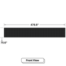
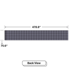
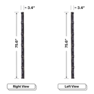
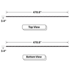
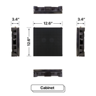
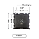
Display Dimensions:

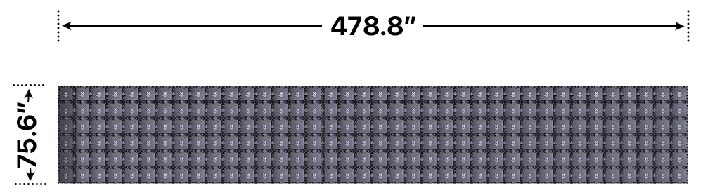

Size-Dependent Specifications: Tailored by Model Dimensions

Screen Size:
6 feet x 38 feet
Actual: 75.6 x 478.8-in
Cabinet Weight:
10-lbs. / sq ft.
Max weight:
(6x38)x10 = 2280 lbs/side
Power use:
95 Watts / sq ft.
196 AMPS@110V or 98 AMPS@220V / Side
Power consumption:
Max 21660 watts
Resolution-Based Specifications: Defined by Display Quality
Beacon HD: P6 MM
Pixel density:
2304 Pixels
Display Resolution:
288 pixels x 1824 pixels
Brightness:
Beacon HD 7000 Nits Beacon HD Pro 8000 Nits
Beacon: P8 mm
Pixel density:
1600 Pixels
Display Resolution:
240 pixels x 1520 pixels
Brightness:
Beacon 7500 Nits Beacon Pro 8500 Nits
Spotlight: P10 mm
Pixel density:
1024 Pixels
Display Resolution:
192 pixels x 1216 pixels
Brightness:
Spotlight 8500 Nits Spotlight Pro 10000 Nits
Universal Specifications: Consistent Across All Models
Media Support:
Images, Videos, Slides, and more.
Communication:
LAN, WIFI, 4G (Optional)

Viewing angles:
110 (V) 110 (H)

Design:
XIGNZ Modular LED Sign
Automatic Sensors:
Temperature and Brightness

Protection Level:
IP65 | UL 48

LED Standard:
DIP SMD 3 in 1

Compatible Devices:
PC, IOS iPhone/IPAD, Android

Aluminium Cabinet:
High-temperature Resilient
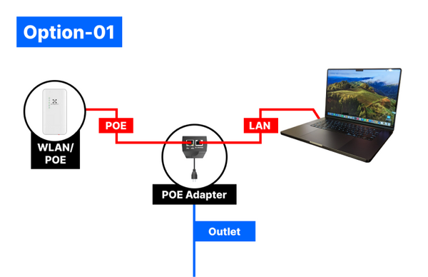
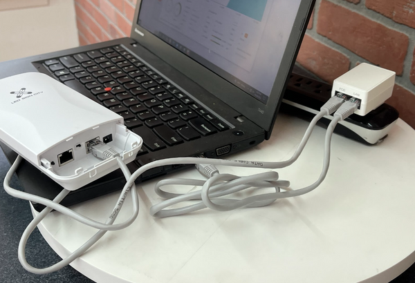
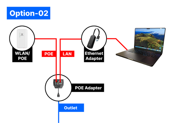
Start using your LED sign right away! Follow the link below, enter your sign dimensions, and instantly receive customized instructions tailored specifically for your sign.