


Assembly Guide
Bringing your LED sign to life involves both careful assembly and secure installation. Follow the guide to unpack and identify parts, assemble the frame, attach LED modules, and connect the necessary cables. Finally, choose the right mounting method and ensure the sign is firmly and safely secured.
How to handle the crate and your LED Sign when unpacking
Tip #1 Always keep the crate upright. Avoid laying the crate flat on any of the sides.
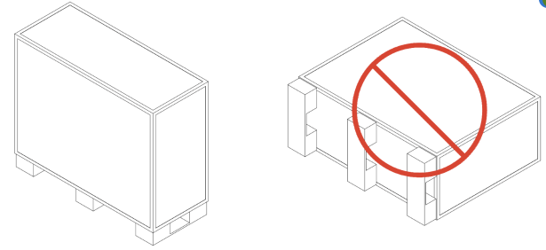
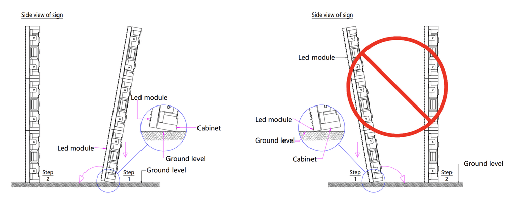
Tip #2 Take care when unpacking the sign and avoid placing the weight of the sign on the LED Modules.
How to assemble your LED sign?
After unpacking the sign, inspect all the included LED Sign sections.
Tools and Parts that will be used in this step:
- 13/14 MM Ratcheting Wrench (not provided
- 17MM Socket (Not Provided)
- Drill / Driver (Not Provided)
- M10 bolts
- M8 Bolts
- X Bracket
Focus your attention on the edges of each section. You will notice that there are three (3) different configurations:
- Cable tunnel is open with a preinstalled rubber seal (ensure rubber seal is in every slot before connecting the M8 bolts.
- Cable tunnel is open with an open center metal gasket preinstalled.
- Cable tunnel is closed with a solid metal gasket preinstalled.
See illustration below.
- The open cable tunnel is the center edge.
- The closed tunnel with solid covers is the outside edges.
For signs with multiple rows, this will also help you identify which sections will be on top.
- The sections with the closed cabled tunnels on top are the top row
- And the sections with the open tunnel on top is the bottom row.
Once you have found the left and right outside edges, arrange your cabinets in the sequence A1, A2, A3, and so on. If your sign has multiple rows, start with the bottom row, then continue by installing the top row in the correct sequence.
Next align the sections linking A-1 to A2 using the provided M8 Bolts.
- You will need two M8 bolts for each cable tunnel. For example, if your sign has three cable tunnels you will need six (6) M8 Bolts.
- Repeat this step until all sections are complete.
- Pay special attention to the front of the sign to ensure that bulbs are aligned as best as possible between sections.

Align the LED Sign Sections
After unpacking your X Series LED Sign, arrange your sign cabinets in sequence so that a clear hole aligns with threaded hole.

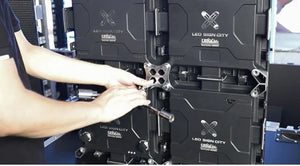
Insert The Bolts
Insert the bolt through the clear hole and screw it into the threaded hole to hold the signs in position. Each cabinet has two holes on the side.

Fasten the Bolts
Use the provided socket to fasten the upper and lower bolts on the side each cabinet.

Attach the X Clip
Place the X Clip in the center of every four cabinets and screw in the bolts to hold the clip in position.
Install the Mounting Brackets
Position the brackets on the back of the sign and use the provided bolts to secure the brackets to the sign (Connect brackets as needed for install).

Lock Sign Sections together
Your LED Sign may arrive in preconfigured sections that you are required to connect together to assemble the required dimensions. Below we will walk you through the steps required to assemble your display and prepare for installation.

Illustration of Complete Assembly
Your assembled sign should resemble the illustration above.
NOTE: For larger signs where the sections will be stacked. You will need to install addition m8 bolts where the cable tunnels on the top of the bottom row, and the bottom of the top row intersect. That’s two bolts for each cable tunnel (before installing, verify that there is a silicone seal on top of the bottom row, and that the open center metal gasket is installed on the bottom of the top row).
After you have connected all the sections, your next step is to install the supporting X-Brackets.
Take note of the pattern of preinstalled X-Brackets. There will be an X-Bracket at the intersection of four (4) modular cabinets. Place the bracket over the hole and use the provide M10 bolts to secure the bracket to the back of the sign.
Tools and parts needed in this step:
- Power cables
- Signal Cables
- Antenna
- Antenna Cable
- Brightness sensor
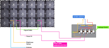
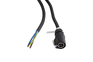
Your power cables are the 13/14 AWG cables with a preinstalled 3 Pin Weatherproof connector on one end. The second end of the cable is either unfinished or has terminal connectors preinstalled.
All Sections, except for the main section, have two power ports, with the labels Power 1 and Power 2. These ports can be used interchangeably. You will connect one power cable to each section. Plug the power cable to Power 1 on the main cabinet, and Power 1 or Power 2 on the remaining sections. One power cable is required per section.
How to identify the main cabinet.
The power 2 port on the main cabinet has been converted to your brightness sensor port. Depending on your configuration, there will be a 9-pin connector or 4 pin connect in the power 2 port on the main cabinet.
The main cabinet is usually on the left side of the sign (when looking at the front of the sign).
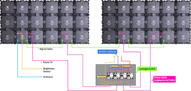
After plugging in your power cables, you will need to terminate the wires to your junction/breaker box (not included). Note the color code for your wires:
Connection for 110V
- Brown/Black – Hot / Live
- Blue/White – Neutral
- Yellow and green/ Green – Ground
Connection for 220V
- Brown/Black – Hot / Live
- Blue/White – Second Hot
- Yellow and green/ Green – Ground
Be sure to secure the power connector to them before turning the power on. And follow proper safety procedures to prevent electrical shock.
Your brightness sensor connects to the Converted / Power 2 on the main section. You will also see the sensor tag on the connector cover. The sensor and power cable use different pin configurations so it’s not possible to the sensor to the power or the power to the sensor.
The antenna connects to the signal 2 port on the outside edge of the sign below the sensor. Your Antenna cable has a 9 pin connector on one end and an ethernet/RJ45 connector on the other end. Connect the Antenna cable to the signal 2 port on the main section. And connect the other end directly into your antenna. (note the included POE injector will not be used at this stage, so do not connect to the sign).
To connect the cable to the antenna, remove the cover at the bottom to reveal the ethernet port. Connect the cover and reinstall the cover. If you opted for the 4G LTE antenna, your antenna may have 2 ports. In this case connect the cable to the WAN Port.
Once they are correctly connected you should immediately see the power lights on the side or front of the antenna depending on your configuration. If there are no lights, check to make sure you connected to the correct port. You should also see the antenna label on the cap on the back of the sign.
When installing the antenna, ensure the antenna is installed vertically with the cable coming from the bottom of the antenna.
-
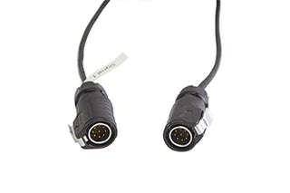
Your signal cable has two 9 pin connectors on both ends of the cable. Start by connecting the signal cable to the Signal 1 port on the main section. Then connect the other end of the cable to signal 2 on the next section. Repeat this step until all the signal cables are connected.
-
For double sided LED signs continue your connection by connecting to signal 1 at the end to the sign 2 on the other side immediately behind signal 1. Then continue your connect from sign 1 to signal 2. At the end you will have a signal 1 port available behind the antenna cable.
Note: if you have a larger sign that has multiple rows of sections. When you get to the end of the bottom row, connect your cable to signal 1 on the bottom row and jump to signal 1 on the top row.
Then connect signal 2 to signal 1 going in the opposite direction as the bottom row. At the end you should have Signal 2 available above the antenna and the sensor. (Imagine making a C-Shaped connection. If you have more than 2 rows imagine making a backward S-Shaped connection that continues until all sections are connected.
Installation Examples
Mounting ideas for your LED sign.
Tools and parts required in this step
Angle Iron (L- Bracket)
Support bar / Frame – Illustrated below but not provided
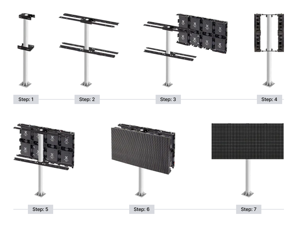
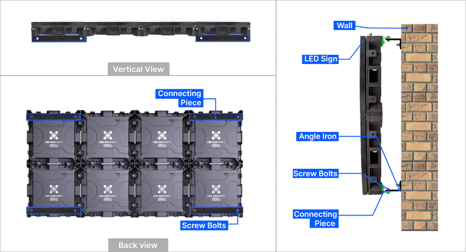
Below are examples of how your LED Sign can be installed. The illustrations provided are for reference only. Always follow your local laws for guidance and construct structure based on required wind load rating and other local requirements.
LED sign installed on a single pole
LED sign installed on double poles: Center-pole mount

LED sign installed on double poles: End-pole mount

Outdoor Wall Mounted LED Display
What's in the box
What's Included in Your LED Sign Package:
Power Cable:
300V-600V outdoor-rated flexible cable equipped with a weatherproof connector for reliable power supply.
Signal cable:
Modified outdoor-rated RJ45 cable featuring a weatherproof connector, ensuring secure and durable signal transmission.
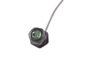
Brightness Sensor:
An automatic brightness sensor adjusts your LED sign's visibility for optimal readability and compliance with local regulations.
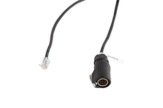
Antenna Cable:
A specially modified RJ45 cable with a weatherproof connector on one end and an Ethernet cable on the other, designed to power your POE CPE antenna or 4G Modem.
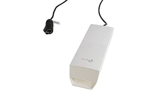
Wireless CPE Antenna:
Choose between a Wireless CPE Antenna or a 4G Modem to guarantee long-range wireless signal connectivity for your sign.
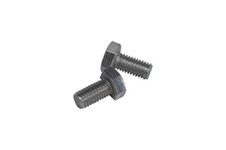
M8 16 MM Bolts:
These bolts are used to securely fasten the sign cabinets together, ensuring maximum rigidity and stability.
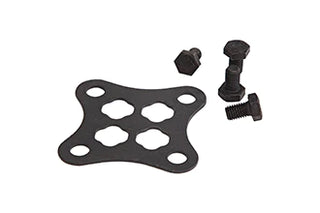
X Brackets & M10 20 MM Bolts:
The X Bracket, paired with the M10 bolt, is strategically placed at the corners where four cabinets meet for added reinforcement.
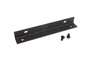
L Brackets & M10 20 MM Bolts:
L brackets come with pre-drilled holes, simplifying your installation process and ensuring a smooth setup.